Python for Prim Properties
A walk through an example python script that creates and works with OpenUSD properties
USD prims store information in prim properties. Properties come in two forms, attributes and relationships. Attributes store values and relationships are like pointers to other prims and properties.
Instead of trying to cover all the details I thought I'd write a script that outputs a USD file to demonstrate the qualities of prim properties. So, let's do that!
What's it gonna do?
We'll make a USD file that demonstrates attributes with static and animated values, and we'll demonstrate relationships by assigning a material. To keep it all pretty simple we'll create two planes, then we'll attach a material with a texture and rotate each plane.
Here's what it looks like rendered with OpenGL/Hydra. I apologize for the weirdness of the colors, I can't figure out gif colorspaces in ffmpeg.
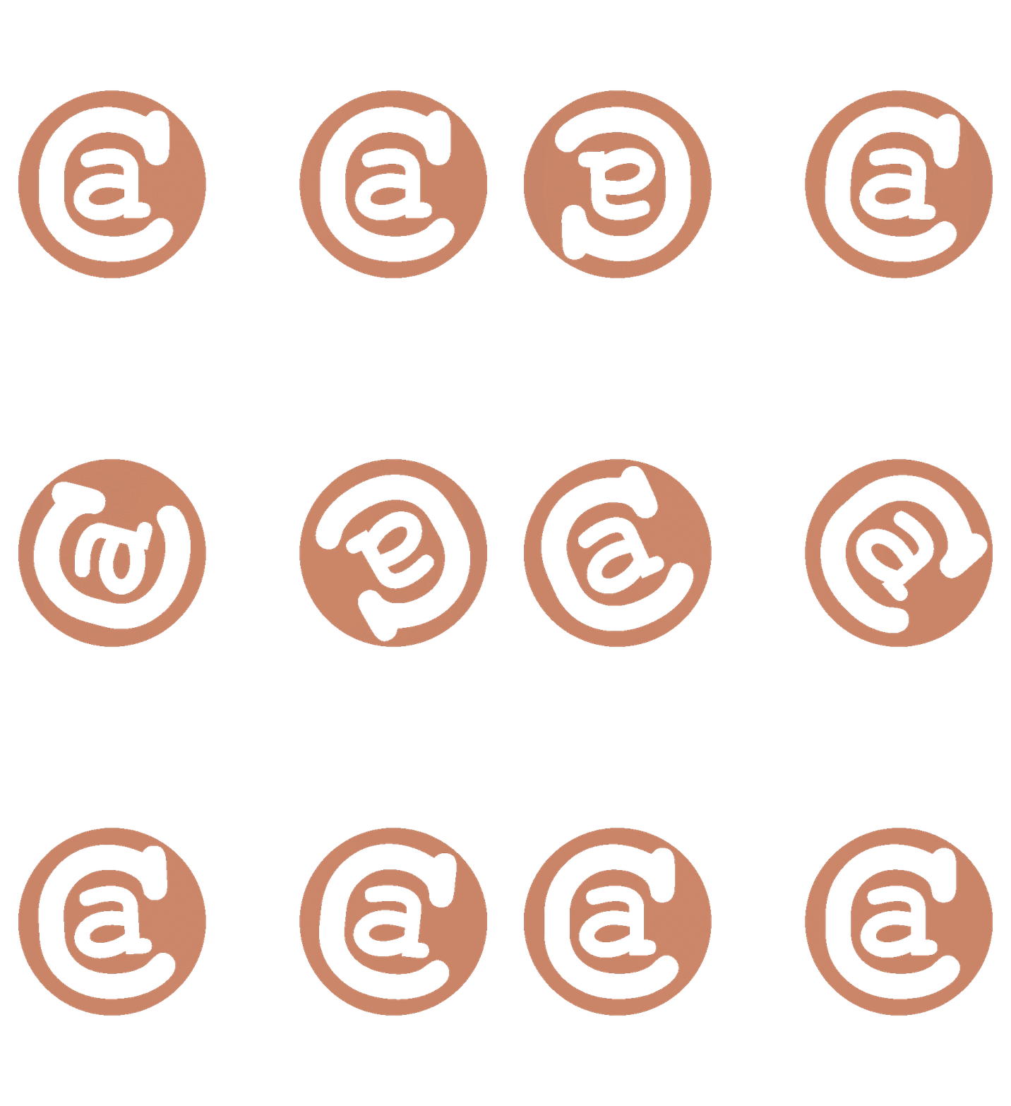
Touring the Code
You can check out the whole script and some related files on github. I'll go over some highlights.
The script starts out with basic housekeeping. We open a stage pointing at a new layer we plan to write out. If the layer exists we overwrite it. We set some metadata, then we add a bunch of prims so we have something to work with. Once that's done we're left with this bit of empty scaffolding.
#usda 1.0
(
    "An example file with attributes and relationships to set"
    defaultPrim = "Example"
    upAxis = "Z"
)

def Xform "Example" (
    kind = "component"
)
{
    def Xform "Left"
    {
        def Mesh "Mesh" {}
    }

    def Xform "Right"
    {
        def Mesh "Mesh" {}
    }

    def Material "Material" {}
}

def Camera "Camera" {}
One thing to notice is that there are no attributes or relationships explicitly set. Each prim implicitly has properties. If we were to get the left mesh and make a call like leftMesh.GetPointsAttr() or leftMesh.GetPrim().GetAttribute('points') that would return a valid points attribute object. The points attribute would just be empty because it's set to its fallback value.
>>> leftMesh = UsdGeom.Mesh(stage.GetPrimAtPath('/Example/Left/Mesh'))
>>> points = leftMesh.GetPointsAttr()
>>> print(points.Get())
None
Mesh Setup
Now that we're set up the first thing we'll do is write attributes to the two Mesh prims. Each mesh will be an identical plane. I used the function below to create each of these. Since they're identical I could have put them into their own USD file and referenced that into each prim where I wanted a plane. I didn't do that to keep the example all in a single file. Each mesh is represented with a single 2 unit quad in the XZ plane, centered at the origin.
def populate_mesh(mesh):
    # We'll hard code some billboards to keep them simple
    mesh.CreatePointsAttr(
        [(-1.0, 0.0, -1.0), (1.0, 0.0, -1.0), (1.0, 0.0, 1.0), (-1.0, 0.0, 1.0)]
    )
    mesh.CreateFaceVertexCountsAttr([4])
    mesh.CreateFaceVertexIndicesAttr([0, 1, 2, 3])
    # function continues...
First this creates and populates the main geometric properties for these meshes. Earlier I mentioned that we could call mesh.GetPointsAttr() and get back an empty Points attribute. Here we called mesh.CreatePointsAttr(...), which might seem a little strange. If there's already an empty Points attribute why would we need to create it?
The answer is that CreatePointsAttr writes a new opinion to the current authoring layer. It's really creating a new attribute value, not the attribute itself (or, possibly more correctly, it's creating an SdfAttributeSpec, not a UsdAttribute). This is safe to do even if there's already an opinion, or if there's an opinion on another layer.
def populate_mesh(mesh):
    # ... snip ...
    tex_coords = UsdGeom.PrimvarsAPI(mesh).CreatePrimvar(
        "uv", Sdf.ValueTypeNames.TexCoord2fArray, UsdGeom.Tokens.varying
    )
    tex_coords.Set([(0.0, 0.0), (1.0, 0.0), (1.0, 1.0), (0.0, 1.0)])
Later in populate_mesh we add UVs to the plane. To add UVs we need to add a primvar. Primvars are special attributes that vary across geometry. The api for primvars is slightly different. When we create this one we name it uv, give it the type texCoord2f[] and indicate it should interpolate over the surface. Then we set the value and we're done making our meshes!
Once that's done each Mesh looks like this in text form.
def Mesh "Mesh"
{
    int[] faceVertexCounts = [4]
    int[] faceVertexIndices = [0, 1, 2, 3]
    point3f[] points = [(-1, 0, -1), (1, 0, -1), (1, 0, 1), (-1, 0, 1)]
    texCoord2f[] primvars:uv = [(0, 0), (1, 0), (1, 1), (0, 1)] (
        interpolation = "varying"
    )
}
Mesh Placement
Next we move each mesh so that they're side by side. We do that by calling this function on the Xform that contains each mesh.
def translate_xform(xf, translation):
    xform_api = UsdGeom.XformCommonAPI(xf)
    if xform_api:
        xform_api.SetTranslate(translation)
    else:
        raise RuntimeError(f"Nontransformable prim {xf.GetPath()}")
Transforms in USD can be expressed in lots of ways, but most 3D creation tools only support a few specific ways to move and position objects. The XformCommonAPI exists to try to be a swiss army knife of transformations. If you use it to write out transforms your content should work in most 3D tools. I've used it here to translate these meshes. SetTranslate added these two lines to each Xform.
double3 xformOp:translate = (1.5, 0, 0)
uniform token[] xformOpOrder = ["xformOp:translate"]
The xformOp:translate attribute says to move the plane 1.5 units in X. The xformOpOrder attribute says in what order transforms should be applied. If there was a translate and a rotate, it would tell us whether the rotation applies before or after the translation. In this case we only have one translate, but you still need the order attribute or it wouldn't be applied. If you use the XformCommonAPI the order will be kept up for you and you don't have to worry about it.
Next up, the Material
The function setting up the material is a bit longer, so I'm just going to talk about some highlights. Here's the full code though.
def populate_example_material(material):
    stage = material.GetPrim().GetStage()
    preview_surface = UsdShade.Shader.Define(
        stage, material.GetPath().AppendPath("SurfaceShader")
    )
    preview_surface.CreateIdAttr("UsdPreviewSurface")
    preview_surface.CreateInput("roughness", Sdf.ValueTypeNames.Float).Set(0.7)
    preview_surface.CreateInput("metallic", Sdf.ValueTypeNames.Float).Set(0.0)
    material.CreateSurfaceOutput().ConnectToSource(
        preview_surface.ConnectableAPI(), "surface"
    )

    uv_reader = UsdShade.Shader.Define(stage, material.GetPath().AppendPath("UVReader"))
    uv_reader.CreateIdAttr("UsdPrimvarReader_float2")
    uv_reader.CreateInput("varname", Sdf.ValueTypeNames.Token).Set("uv")

    sampler = UsdShade.Shader.Define(stage, material.GetPath().AppendPath("Texture"))
    sampler.CreateIdAttr("UsdUVTexture")
    sampler.CreateInput("file", Sdf.ValueTypeNames.Asset).Set("confusing-logo.png")
    sampler.CreateInput("st", Sdf.ValueTypeNames.Float2).ConnectToSource(
        uv_reader.ConnectableAPI(), "result"
    )
    sampler.CreateOutput("rgb", Sdf.ValueTypeNames.Float3)
    preview_surface.CreateInput(
        "diffuseColor", Sdf.ValueTypeNames.Color3f
    ).ConnectToSource(sampler.ConnectableAPI(), "rgb")
    preview_surface.CreateInput("opacity", Sdf.ValueTypeNames.Float).ConnectToSource(
        sampler.ConnectableAPI(), "a"
    )
You'll notice that this function creates a few new prims that weren't in the initial scaffolding. These are shader prims from the UsdShade library, and include a SurfaceShader, UVReader and Texture. The basic idea is that the Material will use the SurfaceShader to get its surface outputs. The SurfaceShader sets some high level values like roughness, then gets its diffuseColor and opacity from the Texture prim, which is a sampler. The Texture sampler talks to the UVReader to figure out how it should map the samples.
We've already seen functions like CreateIdAttr so I won't dig into how those work. CreateInput is a new way to create attributes that's introduced here though. The UsdShade library offers this as a way to create attributes that are set up for shading. The line,
preview_surface.CreateInput("metallic", Sdf.ValueTypeNames.Float).Set(0.0)Results in this usda output,
float inputs:metallic = 0This is mostly a normal looking attribute. You might notice it starts with inputs: even though we didn't specify that. With USD properties anything before a colon is a property namespace. We've seen a few already with xformOp: and primvars:. Namespaces can trigger special handling for certain attributes, and are needed for UsdShade. The CreateOutput functions also set an outputs: namespace.
You may also have noticed a new function ConnectToSource, used like this,
preview_surface.CreateInput("opacity", Sdf.ValueTypeNames.Float).ConnectToSource(
        sampler.ConnectableAPI(), "a"
    )
This adds two attributes to the file, a new attribute called inputs:opacity on the SurfaceShader, and a new attribute called outputs:a on the Texture sampler. If we trim the file to just show those, they look like this.
def Shader "SurfaceShader"
{
    # ... snip ...
    float inputs:opacity.connect = </Example/Material/Texture.outputs:a>
}
def Shader "Texture"
{
    # ... snip ...
    float outputs:a
}
Texture.outputs.a doesn't set a value because the UsdShade Texture shader will populate that value at runtime based on sampling the texture. The inputs:opacity attribute shows a new feature we haven't talked about yet, it makes a connection. Any two attributes can be connected, but in most cases (at least with USD as it works today) this has no actual runtime effect. It just lets software check to see if a connection exists, and do something special if there is one. UsdShade is different though, when it finds a connected attribute it will copy the value of the connection target to the connection source. So in this case, SurfaceShader.inputs:opacity will take its value from Texture.outputs:a.
We also make connections for the SurfaceShader.inputs:diffuseColor, Texture.inputs:st and the Material.outputs:surface.
I think this covers what I wanted to point out in the createMaterial function. So far everything we've talked about has been attributes. Let's look at a relationship now.
Material Assignment
The material assignment function in the example script looks like this.
def assign_material_to_mesh(material, mesh):
    UsdShade.MaterialBindingAPI.Apply(mesh.GetPrim())
    UsdShade.MaterialBindingAPI(mesh).Bind(material)
It's pretty simple. We use the MaterialBindingAPI to do two things. First we apply the API object type to the mesh we want to bind to. That call adds some metadata to the output USD file tagging the Mesh like this prepend apiSchemas = ["MaterialBindingAPI"].
The next line actually binds the material to the mesh. Binding a material uses a relationship called material:binding. We can trim down the output file to show the new lines that were added here, they look like this.
def Mesh "Mesh" (
    prepend apiSchemas = ["MaterialBindingAPI"]
)
{
    # ... snip ...
    rel material:binding = </Example/Material>
}
The rel keyword before the relationship name is how relationships are encoded in USD's text format. In this format it looks a little like the float or token for an attribute type, but in reality this isn't an attribute at all.
The main place you'll encounter relationships is for binding materials, so this is a very typical use case. Relationships can be used anywhere they make sense, and they can point to prims or properties. For the most part though, relationships have no effect unless software is written to interpret and use them.
Animation
With the above code we could write out a static USD file that showed two instances of the texture sitting side by side. I wanted to also demonstrate how time varying information can be written to USD, so I decided to make our meshes rotate.
In the script there's a function called generate_ease_out that I won't copy here. This is already longer than I'd hoped! You can check it out on github if you're interested. It returns a list of tuples. Each tuple has a time code and an Euler angle rotation value. For instance it might look like [(1, (0, 0, 0)), (2, (0, 10, 0)), ...]. For each mesh we'll generate such a list. They rotate in opposite directions, and one rotates twice as quickly. We'll take each of those lists and write them out onto the transforms that contain each mesh. The code looks like this.
def rotate_xform_over_time(xform, rotations):
    xform_api = UsdGeom.XformCommonAPI(xform)
    if xform_api:
        for tc, rotation in rotations:
            xform_api.SetRotate(rotation, time=tc)
    else:
        raise RuntimeError(f"Nontransformable prim {xform.GetPath()}")
First we get an instance of UsdGeom.XformCommonAPI just like we did when moving the two meshes apart earlier. Again, this is to wrap the work of maintaining the xformOpOrder and for writing out values most 3D tools will be happy with.
Next, if we successfully got the api object (I've been pretty lax on error handling in this example, but here's a bit I guess 🤷), we call the SetRotate function on each rotation, and set a time for that rotation value. The SetTranslate function we used earlier also has an optional time parameter. The value should be the timecode at which you want the provided value to be used. Fractional timecodes are allowed.
Here's the output for the left Xform after calling rotate_xform_over_time (trimmed for readability, see github for all of it)
def Xform "Left"
{
    float3 xformOp:rotateXYZ.timeSamples = {
        1: (0, 0, 0),
        2: (0, 17.996582, 0),
        3: (0, 35.38317, 0),
        # ... snip ...
        60: (0, 360, 0),
    }
    double3 xformOp:translate = (-1.5, 0, 0)
    uniform token[] xformOpOrder = ["xformOp:translate", "xformOp:rotateXYZ"]
There are a few new things. The xformOp:rotateXYZ attribute doesn't set a single value the way that xformOp:translate does. Instead it sets a list of timeSamples. Each time sample has a timecode, colon, then the value. Also, notice that the xformOpOrder has been updated to add xformOp:rotateXYZ to the list of transformations being applied.
I don't want to dig in too much on the xform operations here, that would be a long topic on its own. Let's focus on how attributes work, and what this means for animation in USD files.
If an attribute's value type can be interpolated it will be interpolated at points in time where there is no explicit value set. The default interpolation is linear when inside the range of times provided. If you're outside that range, the first or last value is used. USD stages can also be configured to use "Held" interpolation, which means no interpolation.
Time samples don't need to be set on each integer time like I've done here. You could set only a first and last time sample, and you'd get linear interpolation between them. I wanted the rotation speed to change non-linearly for this ease out, so I wrote a value for every frame I intended to render. This is pretty common practice, as is writing out even denser information when needed for subframe interpolation.
In USD's terminology xformOp:translate is set to a Default value, and xformOp:rotateXYZ is set to TimeSamples. It is also possible for an attribute to set both, a Default and TimeSamples. Applications typically request values at a specific time. If there are TimeSamples they'll be consulted first, and if not it will fall back to the Default.
USD also has the idea of the "Default" time, you can access it using Usd.TimeCode.Default(). This is sort of like asking for the value without considering animation. If an application requests values at the Default time and an attribute has a Default and TimeCodes, the attribute will return the Default value. You can use this for things like putting a character in a T pose at the Default time, and also storing a walk animation using TimeCodes.
There are a ton of fine details here, and all of this can be overridden by another feature called Value Clips. If you need to get specific about writing values I'd recommend reading the USD documentation on Value Resolution. It covers in detail what you should get in lots of cases, see the Resolving Attributes part in particular.
While we're on the topic of animation, most animation tools (including Pixar's) can express a lot more kinds of animation than what is possible with time samples. USD doesn't natively support every kind of animation data that's possible, and in my opinion time samples make USD a format for publishing animation, but not authoring it.
There is work ongoing to add more expressive interpolation and the ability to represent attribute values using different types of splines. The feature is called USD Anim and there's a page tracking its progress here.
Oh My God We're Almost Done!
Rounding out the script there is a function that sets up a hard coded camera. I used the Usd.Camera prim's setter function to author all the attributes for us, so there isn't too much interesting from an attributes and relationships perspective to talk about.
In the github repository you'll find a shell script that can generate the example USD file, render the frames and make an animated gif if you have docker and ffmpeg available.
I hope this was helpful. I've tried a few times to write an article explaining Properties, Attributes and Relationships in depth, but it always becomes longer than this (if you can believe it). And it leaves out important information. In the end I thought a guided tour of the most commonly used APIs might be enough, and the docs are there for the deets.
Minutiae, Trivia, and Useless Information
- You can create attributes and relationships with any names and types that are useful, you don't have to stick to the predefined ones. See the Prim.CreateAttribute function for example.
Sdf.Pathobjects can refer to specific properties using dots after the prim name, like/Example/Left.xformOp:rotateXYZ. This is why property namespaces use a colon for the separator, dot was already taken.- There's a reserved namespace called
userProperties:that you can use for custom properties you want to add. This is for digital content creation tools, if they support it they can expose these values in the UI. ymmv - If you want to add new predefined properties, or add behaviors to attributes or relationships, you should check out USD's support for custom schemas.
